Overview
In my previous apartment, I had vertical blinds covering a sliding glass door that I liked to have open during the day and closed at night. Rather than spend 30 seconds each day opening and closing them, I decided to spend 2 months automating it 😁.
The project involved designing and building a mount for attaching an Arduino-controlled stepper motor to the blinds.
Parts of a Vertical Blinds System
To understand how this project works, it helps to understand a few key parts of a vertical blinds system.
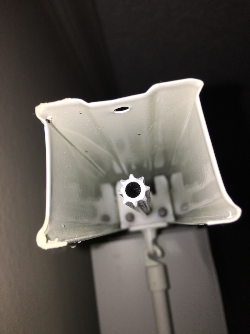
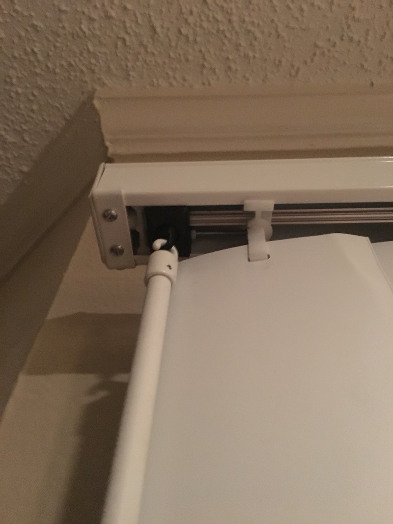
In the above picture, you see the headrail with its end cap removed. The metal rod pointing towards the camera and running the length of the headrail is called the pinion rod. Down the pinion rod you see the wand hanging from the tilt control. When you turn the wand with your hands, the tilt control turns the pinion rod, which rotates the vertical blinds hanging from the pinion rod. This is called tilting the blinds.
The stepper motor is mounted directly to the pinion rod so that it can tilt the blinds open and closed.
Tilt Control
The original tilt control contains a gearbox for creating mechanical advantage between the wand and the pinion rod. This makes tilting the blinds using the wand effortless, but if you try to turn the pinion rod directly you end up fighting the gearbox.
In order for a motor to be able to turn the pinion rod, the original tilt control needed to be replaced. I couldn’t just remove the tilt control because the blinds cover a sliding glass door, and I still needed to be able to use the wand to slide the blinds open. Instead I created a new tilt control which doesn’t interfere with the rotation of the pinion rod.
The new tilt control which has the same dimensions as the old tilt control, but has no gearing and allows the pinion rod to spin freely.
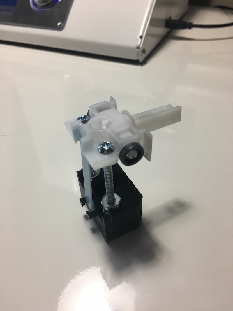
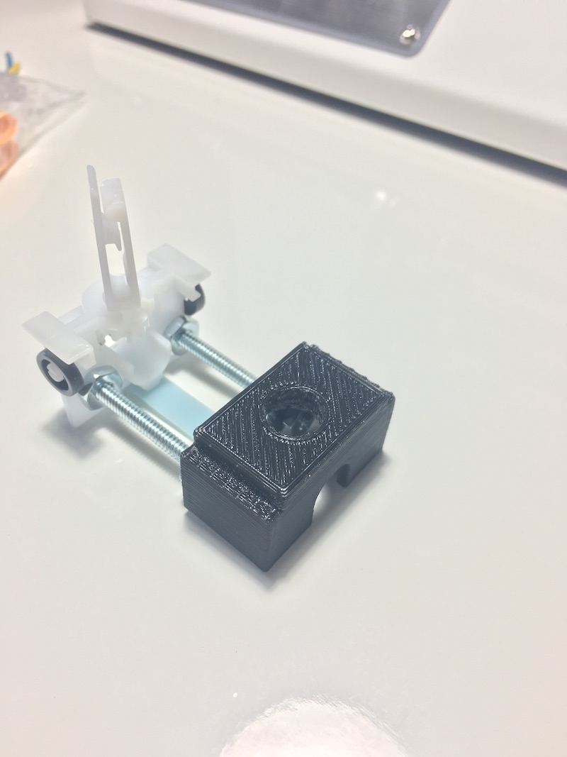
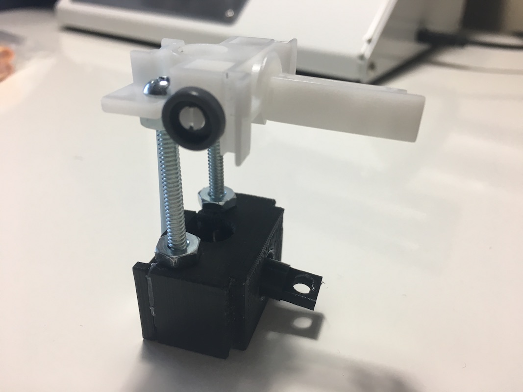
The white plastic part bolted to the new tilt control is the tilt mechanism for the first vertical blind. Each vertical blind is connected to the headrail via a tilt mechanism. The tilt mechanisms convert rotation of the pinion rod into rotation of the blinds.
When you use the wand to slide the tilt control along the headrail, the tilt control pulls the first blind, which pulls the second blind, which pulls the third, etc. along the rail.
The Motor Assembly
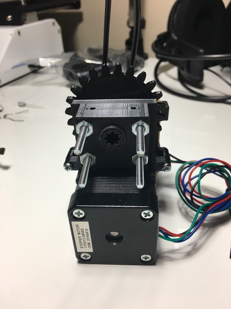
The collection of 3D printed pieces for linking the motor to the pinion rod, mounting the circuit board, and securing everything to the headrail is what I’m calling the “Motor Assembly”. The Motor Assembly was designed with a couple goals in mind:
- Provide a way to link the motor to the pinion rod
- Use gears to assist the motor in turning the pinion rod
- Mount to the headrail using its existing screw holes (no permanent modifications)
- Do so in a compact manner
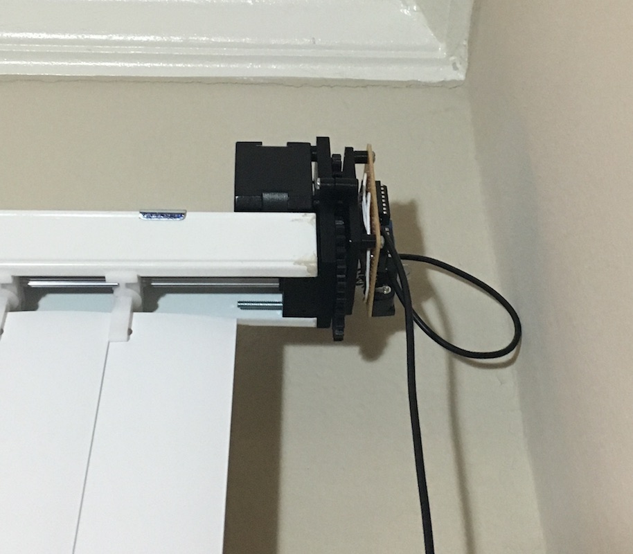
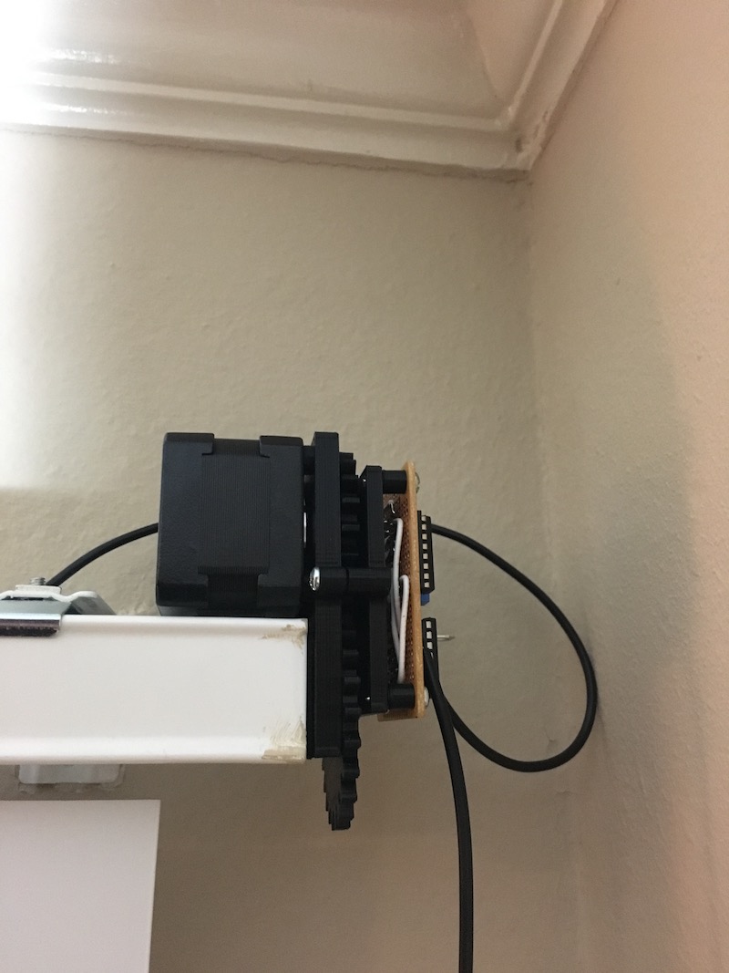
Here’s what I came up with
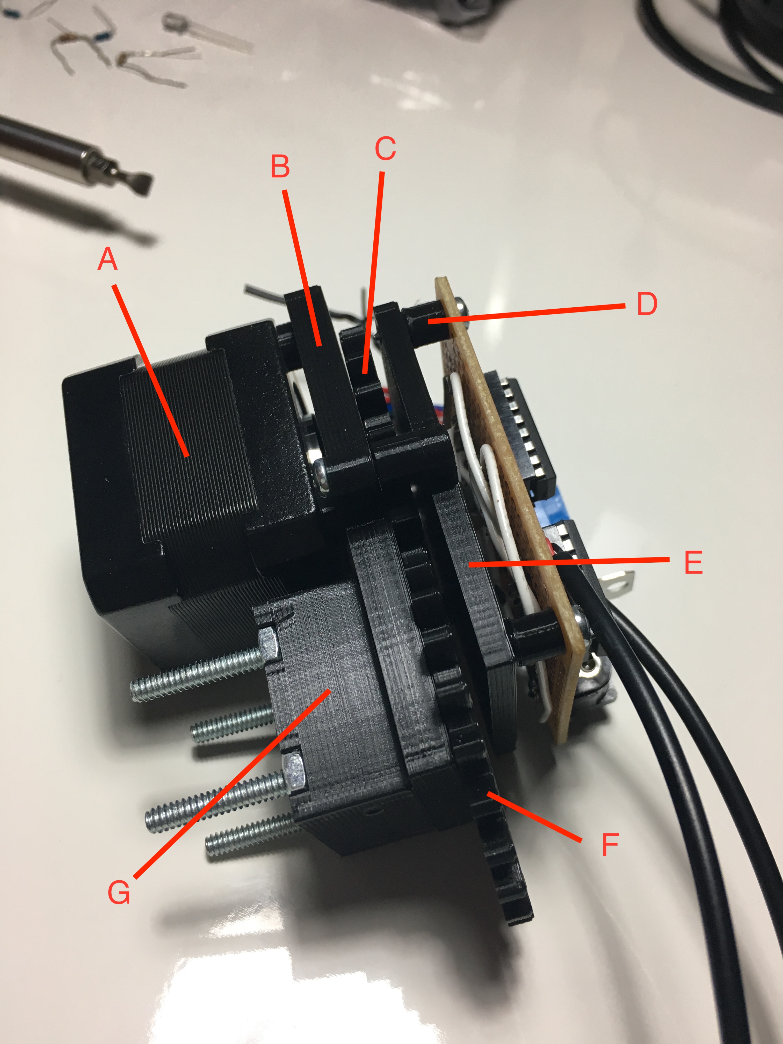
- A - stepper motor
- B - structural plate
- C - 16 tooth gear - connects directly to the stepper motor
- D - PCB standoff
- E - back plate - keeps the gears in place and provides a surface for mounting the PCB
- F - 24 tooth gear - connects directly to the pinion rod
- G - headrail mount - goes inside the headrail and secures the entire assembly to the headrail
Electronics
Circuit Board
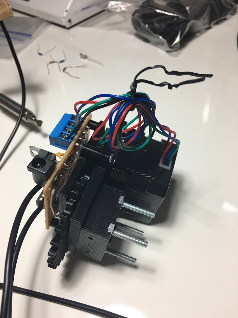
The circuit board has two integrated circuits: an ATtiny84 running Arduino and an SN754410 motor driver. Power is provided via a 12v power supply connected to a DC power jack. The stepper motor is connected to supply voltage while the ICs are connected to the output of a 5v linear voltage regulator.
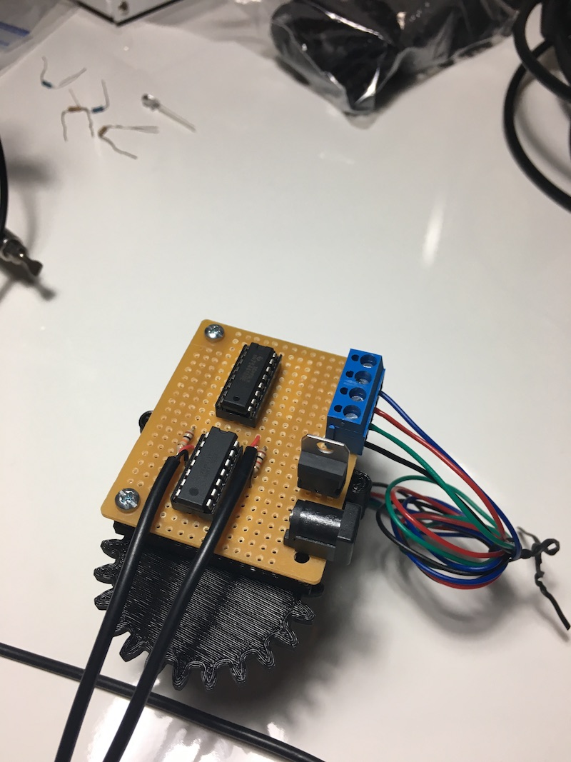
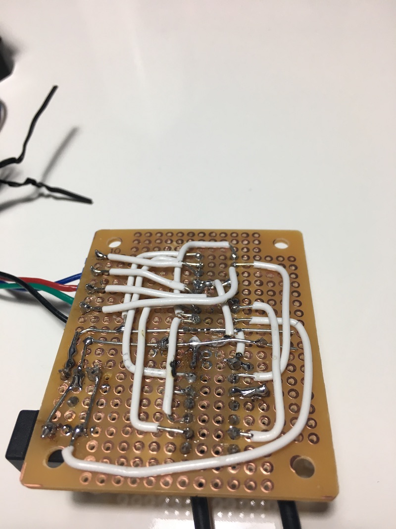
Messy, but it works
Photoresistor
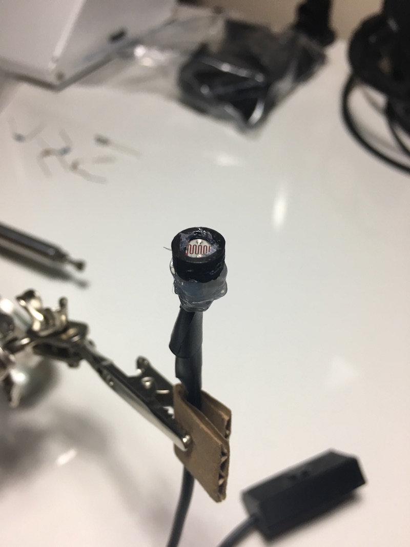
A photoresistor is used to sense the ambient light level outside. The blinds are toggled open or closed when the light level crosses a predetermined threshold and remains on that side of the threshold for at least 3 minutes. Requiring that the light level stay on one side of the threshold for at least 3 minutes prevents the blinds from oscillating when the light level hovers around the threshold.
Button
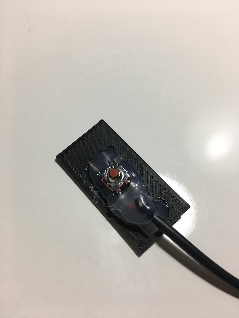
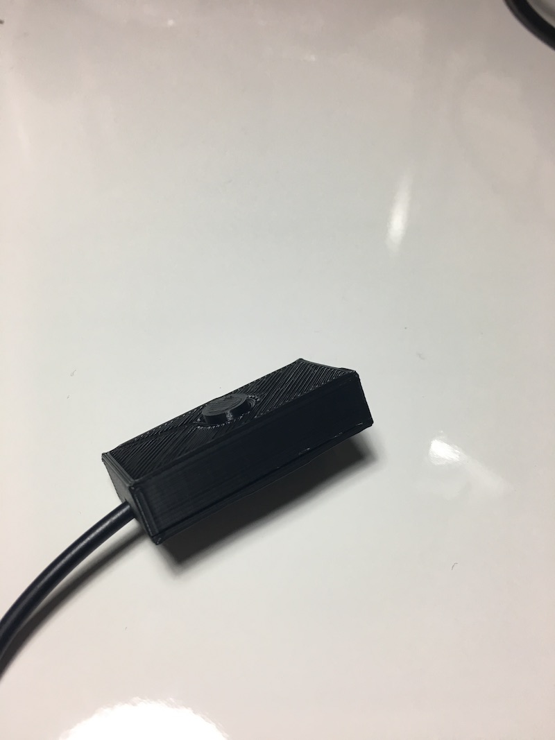
The button hangs down from the motor and lets me manually toggle the tilt of the blinds. It’s just a push button soldered to a 2-conductor wire and glued inside a 3D printed enclosure. The blinds will toggle when the button is pressed, regardless of the light level outside.
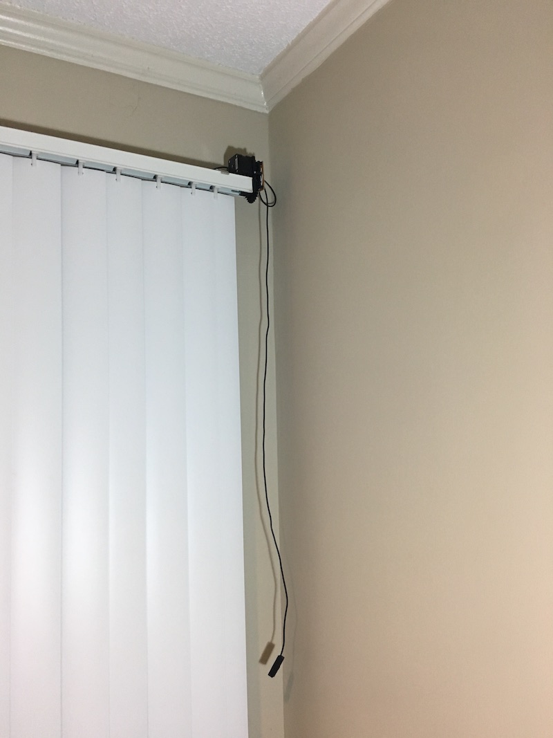
Installation
This is the final result with everything installed